Firefly and PC GAMESS-related discussion club

Learn how to ask questions correctly

sanya
sanya@photonics.ru
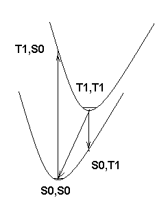
Next, if you look at the attached picture of potential energy surfaces, you'll see that E(C)>E(A)>E(B). However, if the minima on the potential energy surfaces are only slightly shifted from each other, the difference should be rather small. On the other hand, if the shift is so large that emission from T1 minimum leads to a different minimum on the S0 surface, you can get anything. Hence, the second question is, are your A and C values really obtained at the corresponding equilibrium geometries? Do these minima really correspond to the same valley in the coordinate space?
Finally, DFT, even with hybrid functionals, frequently underestimates the excitation energies (either triplet or singlet). Using an exact method (say, CCSD(T)) you will obtain overestimated eneries by A and C methods and correct energy by B. Within DFT, your E(B) is underestimated, while E(A) and E(C) seem to be better due to compensation of errors.
Hope it helps.
On Sat Feb 6 '10 2:36pm, Fumihito Mohri wrote
---------------------------------------------
>Dear All,
>Recently, I have had to calculate T1-S0 energy differences for phosphorescence
> emission spectra (0-0 bands) of some aromatic coumpounds. Then, at first,
>I have tried the calculations for known compounds, using the following methods.
> (A) Delta E(T1-S0)=E(T1,T1)-E(S0,S0), where E(T1,T1) stands for T1 state energy
> at optimized T1 geometry and E(S0,S0) S0 state energy at optimized S0 geometry.
>(B) Delta E(T1-S0)=E(T1,T1)-E(S0,T1), where E(T1,S0) stands for S0 state energy at
> optimized T1 structure. This method is based on Frank-Condon principle.
>(C) Delta E(T1-S0)s were calculated by TDDFT, using optimized S0 geometries.
> Here, the level of theory is B3LYP/6-31G(d,p). The results in eV are listed in
> the following Table. The observed data are taken from R. S. Becker, eTHEORY AND
> INTERPRETATION OF FLUORESENCE AND PHOSPHORESCENCE',John Wiley&Sons,Inc. 1969.
> A B C obs.
>Benzene 3.88 3.31 3.80 3.66
>Naphtalene 2.72 2.30 2.73 2.64
>Antracene 1.81 1.50 1.80 1.85
>2Me-Antracene 1.81 1.46 1.83 1.81
>Carbazole 3.35 3.29 3.19 3.04
>Before calculations,I expected that B would bring the results which are closest
> to the observed values, because when emission of T1->S0 occurs the molecular
>geometry should be kept as one for T1. However, B result is worst among them.
>Moreover, I am surprised with the fact that A and C gives the results close to
> observed ones. Then, I have a question. Why B bring bad results and why A and C
>bring good results ?
>
>
>Thanks in advance,
>Fumihito Mohri
picture of potential energy surfaces of S0 and T1
